Rigid busbar OZh — CuprAl for voltage 10, 20, 35, 110, 220, 330 kV


Purpose
Applications
Rigid busbar is used for installation in 10, 20, 35, 110, 220 and 330 kV open and closed switchgears of power plants and substantions, industrial and facilities of the national economy.
Advantages
- maintenance free;
- easy design and assembly;
- convenient expansion, modernization and disassembly of SG and SS;
- smaller footprint of SS thanks to reducing the area of SG;
- module installation errors can be compensated within a wide range;
- lower location of buses;
- lower construction cost of SS;
- shorter construction periods of SS;
- high seismic resistance – up to 9 points MSK;
- convenient transportation by any means.
Operating conditions
As regards ambient factors, OZh-CuprAl meets the requirements of climatic version NF, location category 1 according to GOST15150-69, GOST 15543.1-89 as well as GOST 17412-72, atmosphere type II; it is designed for use at the altitude up to 1,000 m above sea level.
Content of corrosion active agents must not exceed the values for atmosphere II according to GOST15150-69.
OZh-CuprAl is designed for use under seismic loads up to 9 points at the elevation up to 25 m, 9 points at the elevation up to 10 m MSK-64.
OZh-CuprAl can be used at facilities located at the altitude over 1,000 m above sea level subject to compliance with the requirements of GOST 15150-69.
Structure of marking of OZh-CuprAl
| OZh-CuprAl – | ХХХ – | ХХX / | ХХXX - | ХX | ХХ |
| 1 | 2 | 3 | 4 | 5 | 6 |
1 – rigid busbar made by CuprAl Bridge, LLC;
2 – voltage class, kV;
3 – short-time thermal current of buses for 3 sec, kA;
4 – busbar nominal current, А
5 – main circuit diagram No.;
6 – climatic version and location category according to GOST 15150 and GOST 15543.1.
Example of marking of the busbar type OZh-CuprAl: voltage - 110 kV, short-time thermal current - 40 kA, nominal current 2,000 А, diagram No.4Н, climatic version and location category - NF1:
OZh-CuprAl-110-40/2000-4Н NF1
Technical parameters and characteristics
| Description of parameters | Parameter value | |
| OZh-CuprAl-35 | OZh-CuprAl-110 | |
| Nominal voltage, kV | 35 | 110 |
| Nominal current of busbars, А | 1000; 2000; 3150 | 1000; 2000; 3150 |
| Short time electrodynamic current of buses, kA | 64; 81; 102 | 81; 102; 128 |
| Short-time thermal current of buses for 3 sec, kA | 25; 31,5; 40 | 31,5; 40; 50 |
| Insulation level according to GOST 1516.3-96 | Normal/increased | |
| Test voltage of full lightning impulse to ground, kV: | ||
| -for normal insulation level | 190 | 450 |
| -for increased insulation level | 220 | 550 |
| Maximum wind pressure, m/sec | 32 | |
| Maximum wind pressure in case of ice crusting, m/sec | 16 | |
| Permitted thickness of ice crust, mm | 20 | |
| Busbar diameter, Dnar, mm | 80; 120; 160 | 80; 120; 160 |
| Maximum busbar length, m | 6 | 9 |
| Minimum inter-phase distance of busbars, mm | 1000 | 1400 |
| Installation height of busbars, mm, max. | 4700 | 7400 |
Composition and description of the structure
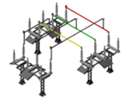
Rigid busbar OZh-CuprAl is a system of current conducting parts (buses) made of pressed circular tubes; they are made of aluminum alloys for electrical applications in accordance with GOST 18482-79.
Each phase of busbars is a bus structure consisting of a series of single-span buses; their ends are fixed on support insulators.
Porcelain or polymeric insulators are used for support insulation.
Busbars are attached to the insulators in horizontal or vertical planes by means of bus holders made of aluminum alloys.
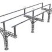
Support insulators are mounted on steel structures; together they form support insulator blocks of various heights and with different inter-phase distance.
Electrical connection between adjacent spans of each busbar phase is arranged by means of current compensators.
The busbar design provides for compensators of thermal changes of the bus length; they have flexible links.
In order to mitigate the impact of wind load on the buses and their supporting structures, a damper device is provided in the rigid busbar. There are drain holes to remove condensate from inside the busbar.
Tube ends are closed with special plugs provided with lock screws.
OZh-CuprAl has collapsible design intended for multiple assembly and disassembly.
OZh-CuprAl offers wide opportunities for design of out-the-box and bespoke, close and open switchgears and transformer substations.
Note. Main electrical circuit diagrams OZh-CuprAl comply with the standard STO 56947007-29.240.30.010-2008 ‘Electrical circuit diagrams of 35…750 kV substantion switchgears’.
Overall, installation and mounting dimensions of support insulator blocks are available upon additional request.
Layout options of OZh-CuprAl for main electrical circuit diagrams of switchgears in accordance with the standard STO 56947007-29.240.30.010-2008 " Electrical circuit diagrams of 35…750 kV substation switchgears’ are available upon additional request.
Scope of supply
Following is included into the scope of supply: tubular buses, support insulators, current compensators, bus holders, clamps for attaching flexible leads. Steel structures for support insulation can be supplied upon additional order.
