GNAC — Generator Neutral Accessory Compartment
Purpose and applications
Three-phase synchronous generators with different power ratings, different cooling systems and different designs have different phase winding connection arrangements, different number of leads of individual phases and different field systems.
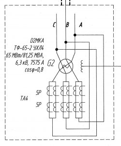
Examples of circuit diagrams of primary circuits for power plant turbine generators are shown in the section ‘Project examples’. Their phase windings may have a star (Y) or delta (Δ) connection. Current measuring transformers are installed in linear and neutral leads of phase windings. Voltage transformers are connected to linear leads of phases. In such cases, one transformer composed of three single-phase transformers will be used most often. Voltage measuring transformers are connected to the leads via circuit breakers and fuses.
In most cases, phase windings in high power generators are arranged in two parallel braches. Each of the branches has a star or delta connection, and connection between the stars is provided via current transformer.
Current measuring transformers of linear phase leads are built into the bus duct, and in case of zero leads, they may be built either into bus duct, or into the generator housing. Current transformers built into zero leads of the generator are installed in each lead, and they may have two, three or four secondary windings.
In order to locate measuring systems and ensure connection of generator leads, our company has develop a dedicated customized module that meets highest reliability and serviceability standards, and has long service life designed for the whole life cycle of the generator. Module GenAir-GAN is produced according to TU-27.12.10-011-90066304-2018.
Standard solutions are available for connection to generators of following suppliers:
- PJSC ‘Elsib’,
- General Electric (‘Russian Gas Turbines’, LLC)
- PJSC ‘Power Machines’.
Nominal parameters
Table 1
Make | GenAir-GAN |
Nominal voltage, kV | 10,5, 20 |
| Nominal current, А | 4000–20 000 |
| Short time electrodynamic current, kA | 250–400 |
| Thermal short-circuit strength for 3 sec, kA | From 100 |
| Cooling type | natural, by air |
| Protection degree | IP 55,IP 65 |
| Climatic version | NF |
| Location category | 1 |
| Atmosphere type at the site according to GOST 15150-69 | IV |
| Storage conditions according to GOST 15150-69 | 3 |
| Transportation conditions according to GOST 15150-69 | 8 |
| Mechanical stability according to GOST 17516.1-90 | М5 |
| Cooling type | natural, by air |
| Сheating temperature for busbars, maximum, °С | +105 |
| Heating temperature for shells and collapsible plug contacts (considering solar radiation), maximum, °С | +80 |
| Seismicity of installation area, points MSK-64 | 8 |
| Rated service life, years | 40 |
| Electrical connection type | Y, Δ |
Table 2
Block type | Nominal voltage, kV
| Nominal current, A | Short-time strength current, kA | Module weight, kg, max.* | ||
| electrodynamic | Thermal, 3 sec. | |||||
1 | 2 | 3 | 4 | 5 | 6 | |
GenAir-GAN-10-3150-128 T3, U3, NF1 | 10 | 3150 | 128 | 50 | 1500 | |
GenAir-GAN-10-4000-250 T3, U3, NF1 | 10 | 4000 | 250 | 100 | 1500 | |
GenAir-GAN-10-5000-250 T3, U3, NF1 | 10 | 5000 | 250 | 100 | 1800 | |
GenAir-GAN-11-3150-128 T3, U3, NF1 | 11 | 3150 | 128 | 50 | 1500 | |
GenAir-GAN-11-4000-250 T3, U3, NF1 | 11 | 4000 | 250 | 100 | 1500 | |
GenAir-GAN-11-5000-250 T3, U3, NF1 | 11 | 5000 | 250 | 100 | 1900 | |
GenAir-GAN-11-6300-250 T3, U3, NF1 | 11 | 6300 | 250 | 100 | 1900 | |
GenAir-GAN-11-8000-300 T3, U3, NF1 | 11 | 8000 | 300 | 120 | 2200 | |
GenAir-GAN-11-10000-300 T3, U3, NF1 | 11 | 10000 | 300 | 120 | 2500 | |
GenAir-GAN-15-5000-250 T3, U3, NF1 | 15 | 5000 | 250 | 100 | 1900 | |
GenAir-GAN-15-6300-300 T3, U3, NF1 | 15 | 6300 | 300 | 120 | 1900 | |
GenAir-GAN-15-8000-300 T3, U3, NF1 | 15 | 8000 | 300 | 120 | 2500 | |
GenAir-GAN-15-10000-300 T3, U3, NF1 | 15 | 10000 | 300 | 120 | 2500 | |
GenAir-GAN-20-8000-300 T3, U3, NF1 | 20 | 8000 | 300 | 120 | 3000 | |
GenAir-GAN-20-10000-300 T3, U3, NF1 | 20 | 10000 | 300 | 120 | 3200 | |
GenAir-GAN-20-11250-400 T3, U3, NF1 | 20 | 11250 | 400 | 160 | 3500 | |
GenAir-GAN-20-12500-400 T3, U3, NF1 | 20 | 12500 | 400 | 160 | 3500 | |
GenAir-GAN-20-18000-500 T3, U3, NF1 | 20 | 18000 | 500 | 200 | 4000 | |
*Block weights may vary depending on their built-in equipment
Design
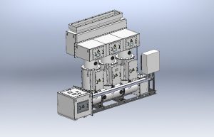
- The electrical generator neutral accessories compartment (GNAC) consists of the air insulated metal housing, in which the equipment is installed such as current transformers, voltage transformers, neutral earthing resistor, anti-condensation heater (in the case the terminal module is installed outside heated premises). All built-in equipment is custom made, and it features the parameters required for the project.
- The GNAC housing is made of aluminum with bolted and welded joints. Internal structural parts of the housing can be made of stainless steel or ferrous metal with powder coating.
- The main power buses are made of tubes.
- The GNAC housing and buses have powder epoxy coating. The main painting color is RAL 7035. Upon customer’s request, a different color may be used.
- Swivel doors are provided for maintenance of the equipment installed inside the GNAC.
- The control board is installed at the bottom and connected with the GNAC by means of cable.
- Fixed mounting is used for all the equipment.
- The GNAC housing in all attachment points is isolated from building structures by means of insulating gaskets and insulation bushings.
- Holes in support assemblies are oval to allow for movements in case of thermal expansions.
- Output buses of the GNAC are connected with generator leads by means of flexible copper links with silver coated contact areas.
Project examples
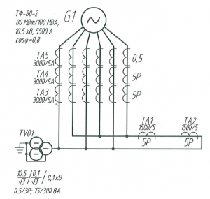
Connection of the generator via the earthing resistor
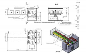
‘Star’ connection of the generator
 | 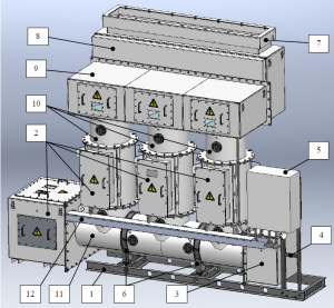 |
1 - supporting frame; 2 - shells with current transformers; 3 – shell with voltage transformer; 4 - relay cabinet frame; 5 - relay cabinet; 6 – removable support; 7 – shell for connection to turbine generator plate; 8 - shell with flexible links and ‘ZNOI’ system; 9 – intermediate shell with busbar; 10 - intermediate shell; 11 - shell with buses; 12 – tray for cable harness.
‘Delta’ connection of the generator
 |  |
