 |
 |
Intended use and applications
GenAir series is Isolated Phase Bus Ducts (IPB) for generator voltages of 6.3; 11; 15 and 20 kV, with compensated magnetic field, designed for nominal current from 1,600 to 20,000 A, are intended for connection of electrical apparatuses at power plants, large substations and main power supply substations of industrial enterprises as well as for 3P AC 50 and 60 Hz circuits between max.1,500 MW turbine generators and step-up power transformers, auxiliary transformers, converter transformers and thyristor excitation transformers of generators.
IP GenAir are manufactured in accordance with TU 27.12.10-007-90066304-2018 replacing TU 3414-001-90066304-2012, according to which the previous TENE and TENP series units were made that are widely used by different industries of the Russian Federation and the CIS countries.
Nominal parameters
- small size — diameter of GenAir exceeds the diameter of cast isolated phase bus ducts by max. 25 % (50-100 mm);
- low weight — GenAir units are 3-3.5 times lighter than similar cast units;
- high degree of protection against atmospheric exposure — IP 67;
- service life is minimum 40 years including the whole service life of the energy facility, and it can be prolonged by means of inexpensive renovation. Insulation of these bus ducts will never wear out;
- integrated measuring systems are maintenance friendly thanks to original technical solutions.
| Type of busduct | Rated voltage, kV | Rated current, A | Resistance, kA | Support insulator pitch | Power loss, 1 kW per 1 run m. 1 phase) | Weight (1 phase), kg/run m. | |
| Electro- dynamic resistance current, kA | Thermal resistance, kA | ||||||
| GenAir-6-2000-128 Т1, У3, УХЛ1 | 6 | 2000 | 128 | 50 | 5000 | 0,12 | 29 |
| GenAir-6-3150-128 Т1, У3, УХЛ1 | 6 | 3150 | 128 | 50 | 5000 | 0,25 | 29 |
| GenAir-6-4000-250 Т1, У3, УХЛ1 | 6 | 4000 | 250 | 100 | 5000 | 0,26 | 31 |
| GenAir-10-2000-128 Т1, У3, УХЛ1 | 10 | 2000 | 128 | 50 | 5000 | 0,12 | 30 |
| GenAir-10-2500-128 Т1, У3, УХЛ1 | 10 | 2500 | 128 | 50 | 5000 | 1,13 | 30 |
| GenAir-10-3150-128 Т1, У3, УХЛ1 | 10 | 3150 | 128 | 50 | 5000 | 0,15 | 32 |
| GenAir-10-4000-250 Т1, У3, УХЛ1 | 10 | 4000 | 250 | 100 | 5000 | 0,26 | 39 |
| GenAir-10-5000-250 Т1, У3, УХЛ1 | 10 | 5000 | 250 | 100 | 5000 | 0,35 | 46 |
| GenAir-15-1600-560 Т1, У3, УХЛ1 | 15 | 1600 | 560 | 20 | 5000 | 0,04 | 50 |
| GenAir-11-2000-128 Т1, У3, УХЛ1 | 11 | 2000 | 128 | 50 | 5000 | 0,12 | 29 |
| GenAir-11-2500-128 Т1, У3, УХЛ1 | 11 | 2500 | 128 | 50 | 5000 | 1,13 | 30 |
| GenAir-11-3150-128 Т1, У3, УХЛ1 | 11 | 3150 | 128 | 50 | 5000 | 0,15 | 32 |
| GenAir-11-4000-250 Т1, У3, УХЛ1 | 11 | 4000 | 250 | 100 | 5000 | 0,26 | 39 |
| GenAir-11-5000-250 Т1, У3, УХЛ1 | 11 | 5000 | 250 | 100 | 5000 | 0,35 | 46 |
| GenAir-11-6300-250 Т1, У3, УХЛ1 | 11 | 6300 | 250 | 100 | 5000 | 0,4 | 50 |
| GenAir-11-8000-300 Т1, У3, УХЛ1 | 11 | 8000 | 300 | 120 | 5000 | 0,45 | 80 |
| GenAir-11-10000-300 Т1, У3, УХЛ1 | 11 | 10000 | 300 | 120 | 5000 | 0,6 | 90 |
| Gen Air-15-2000-560 Т1, У3, УХЛ1 | 15 | 2000 | 560 | 220 | 5000 | 0,06 | 50 |
| GenAir-15-2500-560 Т1, У3, УХЛ1 | 15 | 2500 | 560 | 220 | 5000 | 0,09 | 50 |
| GenAir-15-3150-560 Т1, У3, УХЛ1 | 15 | 3150 | 560 | 220 | 5000 | 0,12 | 60 |
| GenAir-15-5000-250 Т1, У3, УХЛ1 | 15 | 5000 | 250 | 100 | 5000 | 0,28 | 65 |
| GenAir-15-6300-300 Т1, У3, УХЛ1 | 15 | 6300 | 300 | 120 | 5000 | 0,35 | 83 |
| GenAir-15-8000-300 Т1, У3, УХЛ1 | 15 | 8000 | 300 | 120 | 5000 | 0,45 | 89 |
| GenAir-15-10000-300 Т1, У3, УХЛ1 | 15 | 10000 | 300 | 120 | 5000 | 0,64 | 98 |
| GenAir-20-1600-560 Т1, У3, УХЛ1 | 20 | 1600 | 560 | 220 | 5000 | 0,04 | 50 |
| GenAir-20-2000-560 Т1, У3, УХЛ1 | 20 | 2000 | 560 | 220 | 5000 | 0,06 | 50 |
| GenAir-20-2500-560 Т1, У3, УХЛ1 | 20 | 2500 | 560 | 220 | 5000 | 0,09 | 50 |
| GenAir-20-3150-560 Т1, У3, УХЛ1 | 20 | 3150 | 560 | 220 | 5000 | 0,13 | 60 |
| GenAir-20-8000-300 Т1, У3, УХЛ1 | 20 | 8000 | 300 | 120 | 5000 | 0,45 | 89 |
| GenAir-20-10000-300 Т1, У3, УХЛ1 | 20 | 10000 | 300 | 120 | 5000 | 0,64 | 98 |
| GenAir-20-11250-400 Т1, У3, УХЛ1 | 20 | 11250 | 400 | 160 | 5000 | 0,71 | 100 |
| GenAir-20-12500-400 Т1, У3, УХЛ1 | 20 | 12500 | 400 | 160 | 5000 | 0,88 | 125 |
| GenAir-20-15000-560 Т1, У3, УХЛ1 | 20 | 15000 | 560 | 220 | 5000 | 0,65 | 245 |
| GenAir-20-16000-560 Т1, У3, УХЛ1 | 20 | 16000 | 560 | 220 | 5000 | 0,75 | 245 |
| GenAir-20-20000-560 Т1, У3, УХЛ1 | 20 | 20000 | 560 | 220 | 5000 | 1,2 | 245 |
| GenAir-20-22000-600 Т1, У3, УХЛ1 | 20 | 22000 | 600 | 240 | 5000 | 1,1 | 320 |
Design
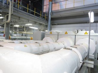
IPB GenAir are metal-clad with isolated-phase arrangement. Such configuration prevents interphase short circuits from ingress of any foreign objects and blocks any human access to live parts of the bus ducts.
IPB GenAir are fully welded along the whole route. The only exceptions are dismountable units for connection to turbine generators, transformers and switches. These units have a riveted frame design that ensures high esthetics, mechanical strength and a high level of protection against atmospheric exposure. Degree of protection is IP 67.
These bus ducts are resistant to electrodynamic forces because they are screened. External magnetic field of the bus duct GenAir is compensated. This is achieved by providing bridges between the isolating housings and by grounding the respective sections of the route.
Detachable contact joints of aluminum multi-ampere cylindrical buses with flat cooper leads of electrical apparatuses are built using highly reliable make-break contacts. In order to compensate any linear changes caused by temperature drops, buses and screening housings of the isolated bus ducts are provided with linear expansion compensators. Support insulators are dew and hoarfrost resistant.
If necessary, attachment units allow for easy replacement of insulators without disassembly of the screens. There is no possibility of sparking (capacitative discharge) in the hollow of the bus duct screens. To this end, special rod-type spring contacts are provided between buses and the top insulator, and in case of vertical layout, they are provided on all the insulators.
Connection joints between screens of the dust protected bus duct and generators or transformers are designed so as to avoid the possibility of overheating of the isolating housings caused by induced currents through transformer caps and generator plates. Thanks to the use of dust protected bus ducts, heating of metal and reinforced building structures located nearby along the route is reduced significantly. This is critical for operation of the dust protected isolated bus ducts laid within the limited space of power plant control rooms.
Bus duct composition and configuration
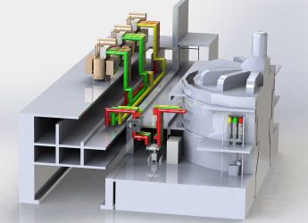
Depending on route configurations and integrated equipment types, the isolated generator voltage bus ducts consist of:
- rectangular blocks (sections);
- angular, Z-shaped, T-shaped and profiled blocks (sections) with integrated equipment (current transformers, voltage transformers, earthing devices, charge arresters, voltage limiters, bushing insulators);
- generator zero lead block;
- generator switch block;
- connection block to power transformer;
- connection joints to line leads of turbine generator, switchboard and MCC;
- butt coupling units between sections and buses, compensators, etc.
Bus duct attachment
Bus duct block beams are welded to building structures. Bus ducts are attached to the beams by means of bolts via insulating bushings.
Screening housings are attached to the cross beams by means of detachable insulated fittings to avoid any circulation of induced currents.
Integrated equipment
In accordance with the circuit diagram, following units are installed together with bus ducts:
1. Generator circuit breakers of various types:
- vacuum circuit breakers 3AH37, nominal current up to 6,300 А and voltage up to 10,5 kV;
- vacuum circuit breakers HB3, nominal current up to 12,500 А and voltage up to 20 kV;
- SF6 circuit breakers HECS and FG, current up to 20,000 А and voltage up to 24 kV.
2. Current transformers of various types including ТВ-ЭК, ТШЛ as well as AOС. These transformers are manufactured according to accuracy classes from 10Р to 0,2S, nominal protection accuracy limit of secondary windings – 5 to 100, and measuring instrument safety rating of secondary windings – FS50 to FS2. Nominal load on secondary windings at cos φ=0.8 ranges from 2.5 VA to 60 VA.
3. Voltage transformers type CTY, secondary windings options – from 100:3V to 110V, as well as the ЗНОЛП transformers that Russian customers are used to.
4. Compact disconnectors and earthing devices 10.5 kV for nominal current up to 5,000 A, with manual and motor drives.
5. Bushing insulators of various types, with porcelain or polymeric insulation, for current up to 5,000 A.
6. Contact joint temperature monitoring system.
7. Overheating indicators and alarm devices.
8. Air drying system.
9. Impact sensors for transportation purposes.
